|
|||
|
|
|
||
| View Shopping Cart |
| Home |
| Guides Available |
| About the Author |
| FAQs |
| Testimonials |
| Articles |
| Contact Andrew |
| Terms & Conditions |
| Mailing List |
| Links |
 |
 |
Get more great articles with every issue of Successful Electrics, the free magazine from Gibbs Guides
Learn more!
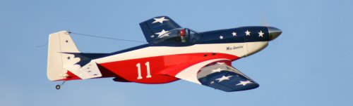
ARF Hangar 9 P51 D
Electric conversion project
Part 2 - Cooling the Components
by Andrew Gibbs
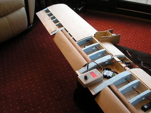
ESC installation
I needed to locate the ESC well forwards, both to keep
the battery to motor wires short, and also to minimise
the possibility of radio reception problems. It was also
important to make sure the ESC received a generous supply
of cooling air. I hit on the idea of mounting it in its
own tunnel through which cooling air would pass. A pair
of balsa spacer rails ensured that airflow would reach
all four sides of the ESC. The tunnel was located between
the firewall and the top plane of the battery box. It
was slightly tricky to fit because I’d already installed
the battery box by this time.
Only the air passing very close to a component produces a cooling effect; any air that passes a significant distance away contributes very little to cooling. The compact dimensions of the ESC tunnel encourage good cooling because cooling air is forced to pass close to the ESC. This principle may be seen in action in U-control (control line) speed models, where the engine is closely cowled yet does not overheat - the relatively small amount of air admitted via the intake passes close to the cylinder head and keeps it adequately cooled.
|
|


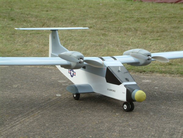
Internal airflow and cooling
Between the air intake and exit, the airflow has been
carefully managed to ensure that the motor, ESC and battery
all receive an adequate supply of cooling air. A few words
about this may be of interest:
All of the cooling air for the motor, ESC and battery enters the model through the chin scoop, a scale feature. A third of this air is ducted upwards straight towards the front of the motor, while the remaining portion is allowed to enter the lower portion of the cowling void.
This intake air leaves the cowling via three routes; some exits via the gaps in the cowl to fuselage joint, some flows into the base of the battery box and the remainder flows into the ESC tunnel.
Both the battery and ESC are fairly snugly located within rectangular balsa tubes. The cooling air is forced to pass close to these components, assuring them of good cooling. Both airflows meet at the top of the battery box and exit it through two holes. From here it passes along the fuselage and out through the exit trough. To permit the air to escape the fuselage, I could have simply cut a hole in its underbelly. However, this beautiful model seemed to deserve something better, so I added a representation of the glycol cooler outlet (radiator outlet) in the open position.
This has the benefit of creating a low pressure area immediately behind it. Air will always flow from a high pressure area to a lower pressure area. The flow of air through the fuselage is therefore driven by two factors:
- Ram air (high pressure) air entering the chin intake
- The low pressure area created behind the radiator outlet.
A further reason to add the glycol cooler outlet was that I hoped its presence might help reduce any positive pressure in the battery box from the ram air, and thus any tendency for the battery hatch cover to separate in flight. The diagrams below illustrate the intended air flow within the model (click images to enlarge).
| This diagram illustrates the flow of cooling air through the model. . | A close up of the motor, battery and ESC cooling arrangements. |


The cleverly engineered design of the full size P51's cooling system is well known for providing additional thrust from the vast amount of heat energy being expelled. It is said that this cooling system thrust was responsible for a gain of around 15 mph. The Mustang is not unique in this regard; other piston powered aircraft also had cooling designs that generated some additional thrust.
However, it would be rather unrealistic to expect any additional thrust from the tiny amount of heat generated by an electric model!
| To direct some of the chin scoop’s intake air at the motor, this balsa and ply deflector was made. | The deflector is seen here tack glued inside the cowling. It was later lightly glassed in position using some scraps of thin glass cloth. |


Care had to be taken to avoid denting the model during assembly. I found that the few dents I did accidentally make were easily removed using a hot covering iron, which stretched the covering over the dent, neatly disguising it.
|
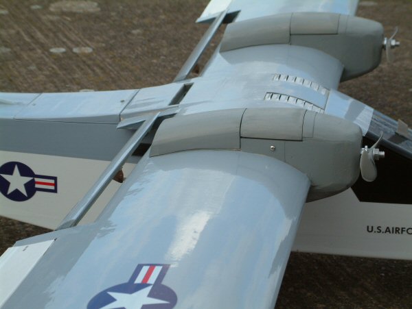
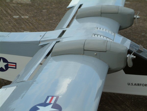
Making the glycol cooler
outlet was a very simple operation. Two holes, just
visible in the picture, were made to allow air to
flow from the fuselage cavity into the cooler outlet
area. |
This simple representation of the glycol cooler outlet was created to assist the flow of cooling air out from the fuselage. The interior is painted gray to disguise the otherwise bare balsa surface. |

