|
|||
|
|
|
||
| View Shopping Cart |
| Home |
| Guides Available |
| About the Author |
| FAQs |
| Testimonials |
| Articles |
| Contact Andrew |
| Terms & Conditions |
| Mailing List |
| Links |
 |
 |
More high quality information absolutely
free with every
Gibbs Guides newsletter. Sign
up now!
Hangar 9 P51 D
Electric conversion project
Part 3 - RC installation and set up
by Andrew Gibbs

RC installation
Standard size servos were used for all of the control
surfaces, and were installed exactly as per the instructions.
Five extension leads were required, one for each servo
and one for the ESC. All of the servos were easily installed
in the intended positions.
Aileron set up
I provided for aileron differential (more movement up
than down), as detailed in the instructions. I also positioned
each aileron with just a slight hint of up (maybe 1 mm,
measured at the trailing edge of the aileron) This effectively
adds washout. Both of these measures are an excellent
idea for models with tapered wings as they help to reduce
any tendency for tip stalling.
RC power
The ESC I had did not have a BEC facility so it was not
able to supply power for the RC system. In any case, for
a large model such as this one, a separate power supply
for RC system power is very worthwhile.
The simplest option would have been to use a single four-cell standard NiMH battery to power the RC system and the associated retract servo. However, any retract system can develop problems and become stalled, and in the case of a mechanical system such as the one installed on this model, this could lead to the battery rapidly becoming exhausted, which would of course lead to a loss of control if this happened with a single battery system.
For this reason I decided I would use a second, separate battery to power the retract servo. To save weight I opted for a pair of separate BEC units for RC system and retract servo power. These are often known as UBEC or SBECs. These weigh only a few grams each, and are designed to supply the radio system with power. The BEC units I used have a maximum input voltage equivalent to a 5S pack, and since the model was to be 6S powered, I decided to supply each of them with power from a small 3S LiPo battery.
The UBECs are of the switching type. Although these are electrically efficient, they do radiate a significant amount of RF interference. The instructions state they should be kept at least 50 mm (2 in) away from the receiver to avoid any possible interference problem from this radiated RF.
|
|


The main RC battery is a 3-cell 800 mAh pack, while the retract battery is a 3-cell 350 mAh example. These batteries provide considerably more stored energy than an equivalent standard 600 mAh receiver pack.
As a comparison, a 4.8 V 600 mAh pack provides nearly 3 Watt hours of energy (0.6 Ah x 4.8 V = 2.88 Wh), while the 3-cell (11.1 V) 800 mAh pack provides almost 9 Wh (0.8 Ah x 11.1 V = 8.88 Wh). This is plenty of energy for a several flights. The smaller 3S 350 mAh retract pack provides 3.88 Wh, again, more than a standard RX pack and sufficient to power the retract servo for many up/down cycles.
The only downside to this LiPo and UBEC arrangement is that preparation of the model is slightly more complicated because the batteries have to be removed for storage and charging.
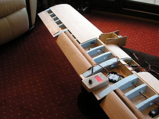
Receiver (Rx) location
A 35 Mhz JR system was used for the model. The receiver
was located at the trailing edge of the wing, at the bottom
of the fuselage. This position kept it spaced well away
from the power system’s components, and the low
position also maximised the vertical component of the
aerial, which should help with signal reception.
| The pair of switches was mounted in the fuselage side. Also seen here is the cover plate which retains the two small lithium batteries. | The receiver is located low down in the fuselage and well away from the BECs and the power system components. |


The receiver is located low down in the fuselage and well away from the dual BECs and the power system components, any of which are possible sources of RF interference. The receiver sits in a bed of foam to protect it and its delicate crystal from vibration. Vibration is still a factor with electric models, and may be generated by an out of balance prop and/or spinner. Take-off and landing also generate vibration as the wheels contact any bumps in the runway.
| A general view of the fuselage interior. | This simple balsa tray keeps the loose RC system wires distanced from the two BECs. |


Spinner problems
I had difficulty in sourcing a scale profile 3½
inch spinner which this model deserved. I settled on a
metal example which was not too far off the required profile.
Out of balance props and spinners show up readily with
electric power models, which don’t have the background
vibration of an i.c. engine.
Since it was a cast item, I was not surprised
to find the spinner body required significant work to
balance it. This was achieved by relieving its inside
surface. Its back plate was balanced separately and also
required a lot of metal to be removed, which was very
surprising as this was a turned item. It was necessary
to make a prop nut on a lathe as this had to have a threaded
M4 hole in its forward end to accept the spinner bolt.
This would not have been needed if I’d used a plastic
spinner of a different design, and with hindsight this
would have been a better option in view of the considerable
time spent on this area. Still, the shiny polished spinner
did look very handsome.
| The cast spinner required a lot of metal to be removed to achieve a balanced condition. | The spinner back plate was separately balanced. As can be seen, a surprising amount of balancing was required considering it was a turned component. Also seen here is the custom-made prop nut. |


Weight and Balance matters
The instructions specify that the CG should be located
4¾ inches (125 mm) behind the leading edge (LE)
of the wing. Unfortunately it was’t specified where
this LE reference point was – the wing is tapered
and has a root fillet, so I was not sure if the reference
point should be the LE at the wing root, an average LE
position along the wing’s actual leading edge, or
the part of the wing which joins to the fuselage. In the
end, I decided that the wing/fuselage joint was the likely
intended reference position. Also, being the most forward
of the options this was a ‘safe’ assumption.
On checking the model in flying trim, I found that my model actually balanced 4 mm behind this position (129 mm behind the wing/fuselage joint). I did not consider this to be a significant deviation and so I was happy to stick with it, especially as there have been a number of reports on internet forums about the model being prone to nosing over on landing.
I also used a useful on-line CG calculator which confirmed that the 129 mm position was perfectly safe.
(I found this at: www.geistware.com/rcmodeling/cg_super_calc.htm)
The ready to fly weight was measured at 3,998 g, or 8.8 lbs. This is a very reasonable weight for a 65 inch WW2 warbird, and was made up of the following:
Fuselage 2,013g
6S battery 768g
Total 3,998g
Static testing
Before committing to the air, the model’s power
consumption was checked. These were the results:
Prop: 15 x 8
RPM: 7,500
Current: 48 Amps
Power: 1,050 Watts
This was well inside the capabilities of the 20C battery which is rated for a continuous 100 Amps, and the ESC which is rated at 70 Amps.
Ground handling
Taxi trials, carried out on grass revealed that there
definitely was a nosing over tendency at low speed. On
very short, smooth grass this was containable with the
use of up elevator. I also found that the undercarriage
legs were a little wobbly in a side to side direction.
This problem disappeared after extending the limit screws
slightly on the retracts. It would have been nice if the
instructions had covered this point.