|
|||
|
|
|
||
| View Shopping Cart |
| Home |
| Guides Available |
| About the Author |
| FAQs |
| Testimonials |
| Articles |
| Contact Andrew |
| Terms & Conditions |
| Mailing List |
| Links |
 |
 |
Get more great
articles like this one absolutely free with every
Gibbs Guides e-magazine. Join
the mailing list!
Electric Ducted Fan (EDF) Models
Part 2 - Ducting design
Article by Andrew Gibbs
Ducting design
The design of the ducting in an electric ducted fan (EDF) model is a most
important issue to get right if the model is to fly well. Poor duct design
can spoil the performance of an otherwise excellent airframe and EDF unit.
Not all commercially produced EDF models feature good quality ducting,
and in fact there are some really terrible duct designs around, meaning
that the motor and fan are drawing huge amounts of power but generating
relatively little thrust.
Duct design is a complex subject, however adhering to some basic principles will go a long way towards getting it right. The basics of good ducting are the following:
Inlet ducting
a) Inlet duct design is in most respects much more important, and more
difficult to get right, than for exhaust ducting. Ideally, inlet ducting
will be designed so that the airflow is smooth, and as far as possible
turbulence-free all the way from the inlet lip to the front face of the
fan. In all cases the duct walls should be as smooth as possible to avoid
promoting turbulent flow. The drag associated with turbulent flow is much
higher than for laminar flow.
b) The area of the ducting should be designed with reference to the fan swept area (FSA) which means the area swept by the blades minus the center body. Intakes of 95% of FSA generally work well.
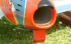
c) It’s important that the inlets have a smooth, rounded intake lip, preferably with a radius of at least 5mm. A very small radius or even worse a sharp edge will promote turbulent flow.
d) Changes in the cross sectional area of the ducting should be made gradually.
e) The air pressure in the inlet duct may become very low under high power, causing a tendency to collapse. The solution is to reinforce the duct so it maintains its shape.
f) Don’t try and make the air change direction quickly. Large radius corners are best.
g) If the inlet ducting diverges, make the angles a shallow as possible to discourage the airflow from breaking away and becoming turbulent.
h) The fan should be installed so that the air flows smoothly all the
way to the fan blades. Don’t have any sharp edges exposed to airflow.
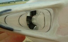
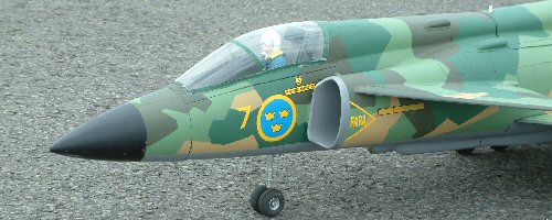
| The rounded lip of this EDF Sabre inlet promotes a smooth, laminar flow of air all the way to the front face of the fan (click small images to enlarge). | The unpainted right hand inlet duct of an EDF Vampire designed and built by David and Will Beavour (click small images to enlarge). |
Exhaust ducting
i) Exhaust air flow will always be turbulent, but nevertheless, drag can
be minimised by making changes in cross sectional area as gently as possible.
j) The exhaust ducting will reduce in cross-sectional area from 100% fan swept area (FSA) to a smaller value at the exhaust nozzle.
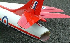
k) The nozzle should not be too small and hence restrictive. Nozzle cross-sectional
areas of around 90% FSA generally work well, but the optimum area depends
on the design of the fan unit itself, the design of the inlet ducting
and the flight speed of the model.
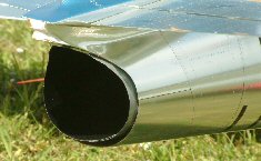
| The cross sectional area of the exhaust nozzle will typically be around 90% of Fan Swept Area (click image to return to original size). | The exhaust ducting of this F86 Saber is clearly visible (click image to return to original size.) |
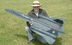
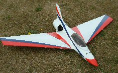
| Nick Butler and his superb EDF SR71. This is a very challenging subject to produce a successful flying model of (click image to return to original size). | The design of this sport model requires only very short ducting (click image to return to original size.) |
Bifurcated ducting
Bifurcated ducting, in which the fan is fed from two inlets, one each
side of the model, is common. Bifurcated duting is a little more complex
to design than straight ducting.
Learn more about EDF ducting here
