|
|||
|
|
|
||
| View Shopping Cart |
| Home |
| Guides Available |
| About the Author |
| FAQs |
| Testimonials |
| Articles |
| Contact Andrew |
| Terms & Conditions |
| Mailing List |
| Links |
 |
 |
Get more articles like
this one absolutely free with every
Gibbs Guides e-magazine. Join
the mailing list!
How to Make a Radio Controlled Opening Canopy
Bruce Smith adds a fantastic scale feature to his P51 Mustang
Intro
This model was the second Brian Taylor P51 I’ve
built. My first model, constructed some years ago had
a canopy which could be opened by hand. However, for this
model I wanted to incorporate a canopy that could be opened
and closed by radio control, giving an extra degree of
building and flying interest.
The canopy needed to slide along a pair of rails, one on each side, just like the full size machine. To power the canopy open and closed, I needed some sort of actuator. This was needed to drive an operating rod in a fore and aft direction, which would push and pull the canopy open and closed. The rod was to be attached inside the canopy at its rear end.
Canopy Rails
I’d solved the problem of a cheap, effective canopy
rail with my previous P51. These were made by cutting
a slot in the top surface of a length of plastic box-section
strip, and running a length of plastic ‘I’
section strip through it.
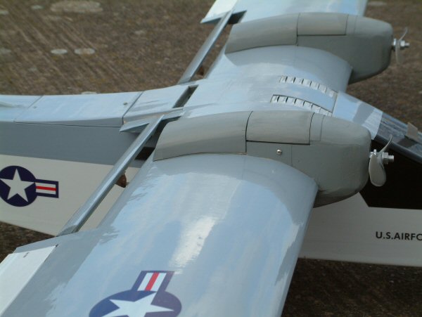
The canopy rails are parallel, allowing the canopy to slide fore and aft easily (click small images to enlarge). |
|


Intro
I decided I needed to design and build a linear actuator
mechanism before I could seriously begin building the
fuselage. I found that industry offered a wide range of
linear activators but these were all either heavy and/or
costly, so I decided to make my own.
My idea was to use a small brushed electric motor and a suitable gearbox to spin a length of M3 threaded studding at a suitable speed, to act as a kind of worm drive. The rotating studding would drive a captive M3 nut up and down according to the direction of rotation. The gearing meant that only a motor of very low power would be sufficient.
I wanted the canopy to open and close at a realistic speed. Weeks of experimentation and research followed to find a suitable motor and gearbox to provide the required worm drive speed. After looking at various options, in the end I built my own gearbox from an inexpensive, readily available over-the-counter kit which came complete with a motor. This was powered by a small single cell Li-Po.
| The inexpensive motor and gearbox unit came from MFA. | The mechanical elements of the linear actuator. |


Actuator electric circuit
Having got the basic mechanism of the actuator to work,
I now needed a way to control it. For this I needed to
draw on the electronic expertise of Andrew Gibbs and Toni
Reynaud to design a suitable electric circuit –
thanks guys.
I carefully wired the system up, and then tested it. It’s only a simple thing, I know, but you’ve no idea just how elated I was when I threw the switch - and it just worked!
Control of the canopy position is accomplished very simply using three switches and two diodes. A two-position servo-operated switch commands the canopy to be either fully open or fully closed by setting the polarity of voltage to the motor. A pair of microswitches define the limits of the actuator’s travel; one microswitch is positioned at each end of the actuator’s travel, and when the captive nut reaches the microswitch it operates, cutting power to the motor. Things are arranged so that when the open/close switch is reversed, power is restored to the motor with the opposite polarity, causing the canopy to move in the opposite direction. A fourth switch is added as a master on/off switch for the system. The wiring diagram shows details of how the motor, switches, diodes and battery are wired together.
Suppression capacitors are fitted to the motor to reduce radiated RF. This is probably unnecessary with 2.4 GHz RC equipment but I added them anyway as it’s such an easy precaution to take.
| The electrical wiring diagram. | The actuator all wired up and ready to test. The motor is powered by the small single cell Li-Po on the left. |


Glycol cooler outlet
Once I’d sketched out a diagram of how the basic
unit might work (see diagram) I realised I’d also
be able to harness the actuator to operate a scale ‘glycol
cooler outlet’ below the belly (real boys’
stuff!). It didn’t seem like adding this would require
much extra work or add much weight, so this additional
function was incorporated into the model.
| This diagram illustrates how the canopy mechanism works. | The operable glycol cooler under construction. |


Installation
Designing the way it would all slip in and out of the
model (again for maintenance) took a lot of thinking time,
but eventually I evolved a very simple solution with two
mounting screws concealed in the rear cockpit. At the
far end, it’s secured with a built in captive nut
which is picked up by some more M3 studding down the centre
of the scale aerial.
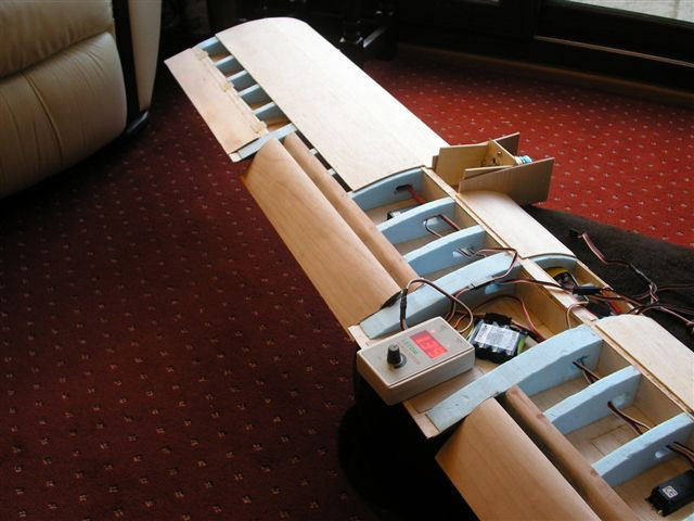
| The canopy fitted in place ready for testing. | The actuator was built in to the model while it was still under construction. Note the limit switches. |


| Here the mechanism has been fitted and is under test. | The main elements of the installation. |


Operation
The canopy is opened and closed by means of a two-position
switch at the transmitter. The canopy and glycol cooler
operate together; when the canopy is open, so is the glycol
cooler.
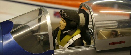
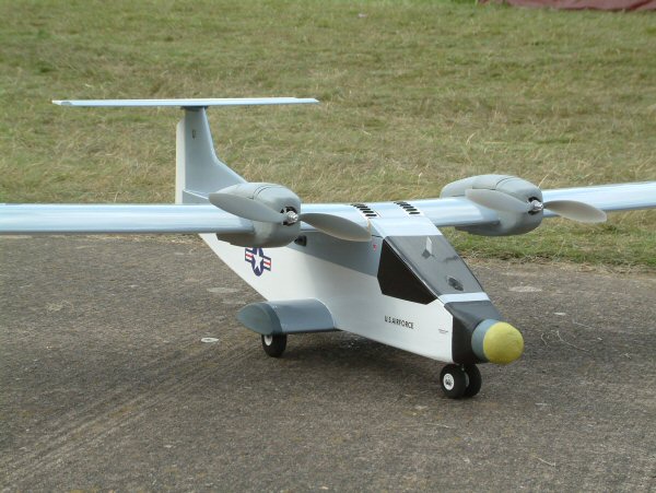
| The opening canopy focuses attention on the cockpit area, so a detailed interior is necessary. | With the model complete, the operating mechanism is completely hidden. The canopy takes about 3 seconds to open or close. |


Conclusion
This was a most satisfying 'project within a project'.
Operating the canopy adds a lot of interest to the model,
and spectators never tire of seeing the canopy and glycol
cooler open and close! The weight of the whole system
is around 4 ounces.
Get more articles like this one
absolutely free with every
Gibbs Guides e-magazine. Join
the mailing list!