|
|||
|
|
|
||
| View Shopping Cart |
| Home |
| Guides Available |
| About the Author |
| FAQs |
| Testimonials |
| Articles |
| Contact Andrew |
| Terms & Conditions |
| Mailing List |
| Links |
 |
 |
More high quality information
absolutely free with every
Gibbs Guides newsletter. Sign
up now!
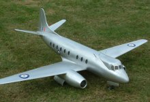
Alan Simmons' Vickers Viscount
Article by Andrew Gibbs
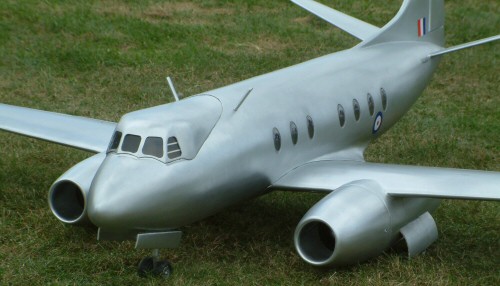
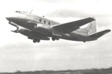
I recently had the pleasure to meet up with Alan Simmons, who had with him a new model of an unusual prototype, a Vickers Viscount. As if that were not unusual enough, it’s a one-off experimental development version of the Viscount, the Type 663 Tay Viscount, which was powered by a pair of Rolls Royce Tay turbojet engines instead of the Viscount’s usual Rolls Royce Dart turboprops.
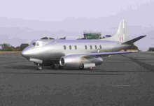
I was surprised to find out how old this design is; the turboprop Viscount first flew in July 1948, while the subject of Alan’s model first flew in 1950. This jet aircraft was the second prototype Viscount and was built as a test-bed. Sadly, the full size machine was withdrawn from use in 1958 and subsequently broken up. However, a number of Viscounts remain in museums and remarkably, three examples are still in service at the time of writing.
Picture was sourced from Wikipedia: |
|
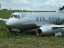
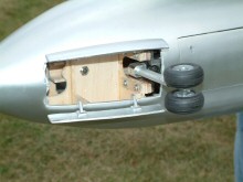
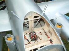
The model is of all balsa construction. Alan chose to model this aircraft both because it appealed to him, and because he thought it would be a relatively straightforward project. However, he discovered that in aeromodelling, as in life, appearances can be deceptive! For example, during the design phase, Alan had to solve the problem of cooling the ESCs. Normally, these would be placed directly behind the fans, but for this twin motored, single battery model this posed a problem. It is unwise to lengthen the battery to ESC leads very much as this can lead to ESC problems, but in order to put the ESCs behind the fans this is exactly what he would have had to have done. The ideal location from the cable length standpoint was to position the ESCs in the wing itself, but this left the problem of cooling them.
|
|
|
|
Alan had the idea that perhaps the ESCs could be cooled sufficiently by having them within the wing, but in firm contact with a metal plate which was exposed to the airflow. The idea was that the ESC would shed its heat to the metal plate, and the plate to the passing airflow. Before finalising the design of the model, Alan carried out a test. He anticipated that the ESCs might well overheat, but was surprised to find that in practice they did not go above 33°C (91°F). Two additional factors make this result all the more remarkable; firstly this was on a static test, without the benefit of cooling air passing over the plates, and secondly the heat shrink covering was left on the ESC’s. Pleased with these results, this design detail was duly incorporated into the finished model, and no ESC overheating problems have been experienced. Alan’s next step will be to use an Eagle Tree data logger to record in-flight temperatures on the back face of the ESC’s, which he expects will be a bit higher.
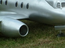
The Tay Viscount’s nacelles looked particularly slim although this was something of an illusion created by their length – the centrifugal turbojets were fatter than the later axial designs, but Alan had to make the nacelles a bit fatter than scale to allow for the 72mm outside diameter minifans to be accommodated at the chosen scale. The intake and exhausts are enlarged by a smaller proportion, the result being that the ducting is divergent towards the front face of the fan, and convergent toward the tail pipe. This is common with EDF models, and has proved no problem in practice.
|
|
|
|
|
|
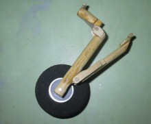
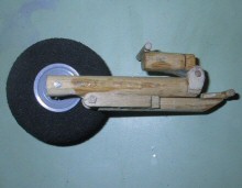
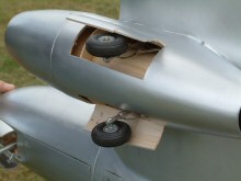
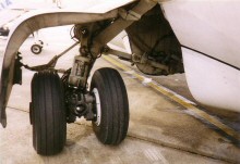
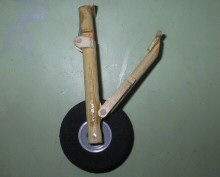
The main gear is also squeezed into the nacelles. At present the undercarriage is fixed, although as can be seen above, an ongoing project is to make it retractable. Each nacelle houses two separate gear legs. Each leg has a single wheel, and will retract either side of the jetpipe. As per the prototype, the gear legs will be made to shorten as they retract. This particular detail means that the work required is of a complexity that renders the gear a separate project in its own right. This will be a design challenge, but I am sure Alan is well up to the task. Shortening gear legs are found on a number of aircraft including the BAe146 (see photos above).
For energy, the model carries a single 3-cell 4,800mAh LiPo battery, from which both Mega 16 series EDF motors are fed. At full power, the battery voltage falls to about 10V, with each motor drawing about 35 Amps. The total current draw is thus 70A, equating to a power consumption of around 700W. A current of 70A from the high performance 4.8Ah battery represents a discharge of under 15C, so the pack is not unduly stressed.
The model is still under development, and had only been flown once or twice when I saw it. However, Alan reports that two minutes of flight uses about 1,400mAh from the battery, so the expected practical maximum flight time is around 5 or 6 minutes.
The fan rpm is estimated like this; the motors have a kv of 3,350, so on 10V the no-load speed would be 33,500rpm. This can be multiplied by about 0.8 to estimate the actual rpm, giving an estimated figure of 26,000rpm. It would be interesting to compare this to a actual measured figure.
| Vickers Viscount power system data 1 x 3S 4,500mAh LiPo |
|||||
| RPM (approx) | Voltage | Current (Amps) |
Power (Watts) |
Pitch speed | |
| Full throttle | 26,000 | 10 | 70 | 700 | n/a |
| Cruising flight | TBA | TBA | TBA | TBA | n/a |
|
|
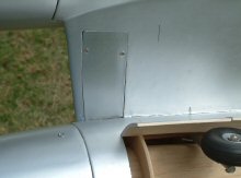
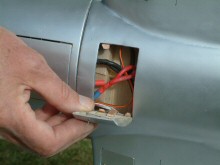
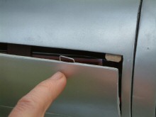
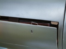
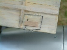
Alan's model incorporates a number of hatches. I was impressed at how simple and effective these were, adding very little weight to the airframe. The next few photos detail how these were made.
|
|
|
|
Finally, here is a summary of the technical data for this fine model of the Type 663 Viscount:
| Tay Viscount technical data | ||
| Span | 1,571mm | 62 inches |
| Length | TBA | TBA |
| Flying weight (1 x 4,500mAh 3S LiPo) |
2,500g | 5lb 8oz (88oz) |
| Wing Area | 0.29 sq m | 449 sq in |
| Wing Loading | 00g/dm | 28 oz/sq ft |
| Batteries | 1 x 4,500mAh LiPo | |
| Motors | 2 x Mega ACn EDF; 2 wind, 6 pole | |
| EDF unit | 2 x WeMoTec Minifan | |
| Max Power | 700W | |
| Power Loading (max power) | 286W/kg | 130W/lb |
| Power Loading (average power) | TBA | |
| Control functions | Rudder, elevator, ailerons & throttle. Retracts are under development. | |