|
|||
|
|
|
||
| View Shopping Cart |
| Home |
| Guides Available |
| About the Author |
| FAQs |
| Testimonials |
| Articles |
| Contact Andrew |
| Terms & Conditions |
| Mailing List |
| Links |
 |
 |
Join the thousands of modellers who receive Successful Electrics, the free high quality electronic magazine:
Click here to join the mailing list
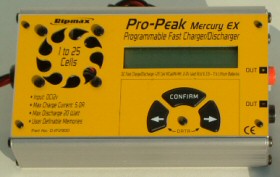
How To Restore An Unresponsive Charger Back To Health
by Andrew Gibbs
|
Many chargers have their operating switches mounted directly on the unit’s printed circuit board (PCB). These switches are operated by panel mounted buttons. Over time, the switches can become clogged with dust and dirt, which may cause them to work poorly and unreliably. Eventually the charger can become quite difficult and unpleasant to use, requiring a high pressure on the buttons for any kind of response. The switch may become so dirty that it fails to work at all, and appears broken.
This short article describes how I restored my LiPo capable Mercury EX charger back to full health simply simply by cleaning its dirty PCB mounted switches. It turned out to be a very quick maintenance job which yielded a great result. The same technique may be also be applied to other chargers such as the Super Nova, FMA Super Nova and many others.
This work requires the charger to be opened up. Clearly this will invalidate the manufacturer’s guarantee, so it’s probably only of interest for old equipment. My charger was well out of guarantee and wasn't working properly - so I had nothing to lose!
|
|


Equipment
Very little equipment was needed for this project. I used
the following:
1. Suitable screwdrivers.
2. A spray can of switch cleaning fluid (such as Servisol)
with a suitable applicator tube. This is available from
electrical supply shops for £3 ($5) or so.
3. Eye protection
NB Make sure that you use switch cleaning compound and nothing else – sprays such as WD40 oil are totally unsuitable.
Safety precautions
I always feel it’s important for health not to breathe
in any vapours, over spray or splashes from synthetic
compounds such as paints, glues or the switch cleaning
fluid I used for this job. I have an efficient extractor
fan plus an extract hood at my workshop, but I could also
have chosen to work outside if this had not been available.
When spraying the cleaning fluid I also wore eye protection
in case of unexpected splashes.
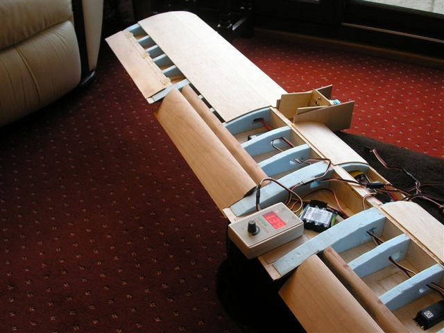
| Inside the charger. The front panel to which the fan is attached has been completely removed. The end panels have been left loose for now. The PCB is low down in the case. | Switch cleaning compound is sprayed at the PCB mounted switches. These are the small black square shaped items. This picture shows my first attempt, without an applicator tube. This didn't work well. |


The procedure
I’d not dismantled my charger before so I was not
sure where to start. I decided to begin by detaching the
charger’s end panels. However, this didn’t
provide enough access to the PCB, so I removed the front
panel as well. In my case the four screws at the panel
corners had to be removed to accomplish this. I placed
all the screws in a suitable receptacle so they didn’t
get lost.
Upon lifting the front panel, I found that it would not come away very far, which made access to the PCB still difficult. This was because the fan, which was attached to the underside of the front panel, was still connected to the PCB by a short length of cable. I disconnected this, which allowed me to fully remove the front panel.
The front panel also housed the three black plastic buttons which operated the switches directly below them. I now had the required easy access to the PCB. Inside, I found that the electrical switches which operated the charger were, as expected actually attached to the printed circuit board (PCB). They were operated by the three black plastic buttons located on the front panel.
To clean the switches it was necessary to direct some switch cleaning compound (definitely not WD40!) into to the switch’s interior. I first tried to do this by spraying in the general direction of the switch, but I wasn’t confident that any of the fluid had actually reached the switch’s interior.
By using an applicator tube I was able to apply the cleaning fluid under pressure directly into the switch. Only in this way was I confident that some of the cleaning fluid had got right inside the switch and, I hoped, dislodged any dirt that had accumulated there. I made several short squirts and to assist the fluid in reaching the switch contacts, I felt it helped to wobble the switch while spraying.
After applying the fluid, the charger was left outside for several hours to dry out. The fluid evaporates quickly so this time period could probably have been reduced to just a few minutes or so, but I wasn’t in any rush. In the meantime I took the opportunity to clean up the charger's yellow front panel. I then re-connected the fan to the PCB, and replaced the front panel, making sure that the plastic buttons mated correctly with the PCB mounted switches.
The end result
Upon testing it, I was delighted to find that the charger
worked beautifully again, requiring only a very light
press of the buttons for a positive response. Excluding
drying time, the total time taken for this job was only
a few minutes. The job was so quick and easy that I wondered
why I hadn’t done it much sooner! And of course
in these recessionary times, repairing equipment instead
of replacing it is a particularly attractive idea.
*********
Response from Mark Moran
Hi Andrew. I read your recent article with interest as, about a fortnight ago, I too decided to tackle the infuriatingly intermittent Start button on my Lipro Plus 5 "Four Button" charger. Having got the two end plates unscrewed I found that the four buttons themselves were stopping the PCB from sliding out and I couldn't see how to overcome this. I needed to use the charger too so I just squirted Servisol at what I could see of that button, hoped for the best - and it worked!
| Mark Moran's LiPro Plus charger in a dissassembled state. | The charger's circuit board. The four switches which the buttons press down on are the row of four black dots along the bottom of the board. |


However, having just read you article I decided to have another go. To cut a long story short, having tried a couple of things, a pair of needle-nosed pliers had just enough grip to pull each button top off its switch free of the case and the PCB then just slid out. A squirt on each switch was now easy and having re-assembled the board and lined up the switches with the case holes the buttons just pushed on. Buttons and switch tops are both made of plastic however so this will probably not be repeatable too many times. Hopefully though it won't be necessary! You might like to add this"Button removal" idea to your article. Servisol is certainly the way to go.
Join the thousands of modellers who receive Successful Electrics, the free high quality electronic magazine:
Click here to join the mailing list