|
|||
|
|
|
||
| View Shopping Cart |
| Home |
| Guides Available |
| About the Author |
| FAQs |
| Testimonials |
| Articles |
| Contact Andrew |
| Terms & Conditions |
| Mailing List |
| Links |
 |
 |
Get more high quality electric modeling information, absolutely free:
Sign up for the Gibbs Guides newsletter now!
Electric Flight Glossary
& discussion of electric flight terms
Part 4 - R to Z
by Andrew Gibbs
There are many technical terms and words relating to model
aircraft in general, and electric flight in particular.
The aim of this detailed glossary is therefore to offer
an accurate and detailed yet concise explanation for any
of the terms the electric modeller is likely to come across.
Let us know if a term you'd like to see covered is not
discussed here!
Receiver battery
The receiver battery is a separate battery used
to supply power to the receiver and servos in a
model airplane. For an electric powered model, a
receiver battery is not required if power is supplied
via a BEC from the main flight battery.
Resistance
Resistance is the term given to opposition to current.
Using the analogy of water flowing through a hosepipe,
resistance may be represented by a restriction in
the pipe. The hose itself will provide some resistance
to the flow; the longer the hose, and the smaller
it is, the greater the resistance will be. The same
holds true for electrical wire; the longer this
is, and the smaller the cross-section of the wire,
the greater the resistance to electrical current.
Resistance is measured in Ohms.
Motors, ESCs and batteries all have electrical
resistance, and therefore all generate a noticeable
heat in use, especially in high power set-ups. The
heat is generated when a current is made to flow
through a resistance.
Electrical
resistance causes heat to be generated in
electric flight components such as motors,
ESCs and batteries. |
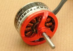
The
rotor of a brushless motor consists of all
the rotating parts. For the outrunner, this
means the case with the attached magnets plus
of course the propeller shaft. |
Rotor
The rotor is the name given to the moving components
of a brushless electric motor. In an outrunner,
the rotor consists of the case to which the magnets
are attached. The rotor of an inrunner comprises
the shaft and the magnets which are attached to
it.
RPM/V or RPM per Volt
See the entry for Kv
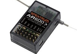
Receiver, Rx
Rx is an abbreviation for receiver. The receiver
decodes the transmitter signal detected by the receiver’s
own aerial, and sends the required commands to the
servos.
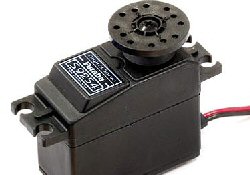
The
position of the servo output disc will follow
transmitter commands, allowing a model to be
accurately controlled. |
The
receiver detects the transmitter's signals,
and passes its commands to the servos. |
Servo
A servo is an electro-mechanical device used to operate
a model’s control surface. The servo takes a
command from the receiver, amplifies it and powers
a small highly geared electric motor to move an output
arm. The servo also contains a feedback potentiometer
so it ‘knows’ when it has reached the
required position.
Shock Flyer, shocky
This is the generic name given to small,
highly aerobatic indoor models typically made from
Depron or other foam. The name probably came about
because the models were almost shocking to witness
when they first appeared late in 2003. Since then
the genre has been developed and it is now a popular
form of indoor RC flying.
Slotted / Slotless Motors
A brushless motor in which the windings are wrapped
around “teeth” in the stator is known
as a slotted motor. The windings may also be wrapped
completely over the stator ring. Motors built in this
manner are known as slotless motors.
An easy way to tell the difference between a slotted
and a slotless motor is to turn the motor shaft. A
slotted motor’s rotor poles are magnetically
attracted to the “teeth” on the stator
plates. You’ll feel a detent, slip, detent in
the shaft as it turns, this is known as cogging. A
slotless motor doesn’t have teeth, so there’s
nothing for the magnets to pull on, thus no cogging.
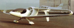
The
spinner streamlines the front of the model.
Visually, it is a very significant part of any
scale model. |
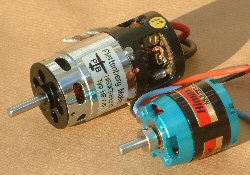
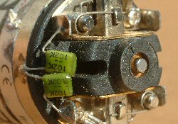
This
brushed motor is fitted with suppression capacitors
to reduce the amount of radio interference radiated
by the motor. |
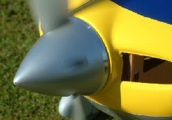
Spinner
The spinner is the cone-like fairing fitted to the
propeller. For scale models, it is important that
the spinner is of the correct profile, otherwise the
impression that the model is a miniature version of
the real thing is spoiled.
Stall
The wing of an model aeroplane is angled
at a few degrees to the the oncoming air in normal,
level flight. The angle at which the wing operates
is called the angle of attack. The angle of attack
will vary depending on the flight conditions. Consider
the case of an model flying at different speeds, but
maintaining level flight. At cruise speed the wing
will be at a low angle of attack, perhaps 3 degrees
or so. As the airspeed is reduced, the angle of attack
must be increased so that the wing can continue to
produce lift equal to the weight of the model. At
low speed, the wing will be angled at perhaps 12 degrees
or more.
If the model is slowed still further, the angle of attack will increase even more, until at some point the majority of airflow over the upper surface of the wing will start to break away, and the wing will be unable to produce lift equal to the weight of the model. In this condition, the wing is said to be stalled, and the wing has reached its critical angle of attack.The critical angle of attack is typically around 15 degrees.
Stator ring
This is another name given to a flux ring. See the
entry for flux ring.
Suppression capacitor
Suppression capacitors are fitted across the motor
terminals of brushed motors to reduce the radiated
electrical noise (interference) from the motor. The
electrical noise from a brushed motor is generated
at the interface between the brushes and the commutator.
Suppression capacitors are not used with brushless
motors.
SBEC
See BEC
Timing
Explanation to be added
Tip stall
When a wing reaches its critical angle of
attack, it will stall. However, not all parts of the
wing will stall at the same time. When a wing stalls,
the wing tip may tend to stall before the inboard
part. This is known as a 'tip stall'. The more heavily
tapered a wing is, the more likely it is that the
wing will stall at the tip first.
Torque
Torque is the name given to a turning, or twisting
force. Torque is defined as a force multiplied by
a radius (distance). Torque therefore has to be defined
in terms of both of these units, for example ounce-inches
when defining a relatively small force, or pound-feet
for larger forces.
An example of a relatively low value of torque could be a servo which might have a torque of 80 ounce-inches. This means the servo can develop a torque equivalent to an 80 ounce force at a radius of 1 inch (80 x 1 = 80) or a 160 ounce force at half an inch (160x0.5 = 80). As we can see, the torque is expressed taking into account the distance and the force. We can’t define a torque using only one of the units.
Another practical example of torque is when using a wrench to tighten a propeller nut. For example, we might apply a force of 10lbs. If our hand gripped the wrench at a distance of 6 inches from the nut, the torque applied would 5 pound feet (10 x 0.5 = 5).
Thrust
The propeller generates a force called thrust which
drives a model forward. There are two types of thrust;
static thrust and dynamic thrust. Static thrust is
the thrust we can feel the propeller generating when
the model is stationary. Conversely, dynamic thrust
is the thrust which the prop generates with the model
at flying speed.
Unless the model is in a zero airspeed condition, such as when hovering, dynamic thrust is the only value of importance. Static thrust may easily be measured by means of a force measurement device such as a simple spring balance. Unfortunately, measuring the static thrust of propellers tells us literally nothing about the likely flying performance of a model. However, thrust measurements for EDF models do have some use. Unfortunately, without a wind tunnel dynamic thrust is impossible to measure.
You can find much more useful information about props in More Than Motors, available here
Turns
This refers to the number of times the windings are
wound around the armature of a brushed motor, or the
equivalent in a brushless motor. A single wind would
be once around the shaped armature, two winds twice
and so on. Varying the number of turns of wire in
the coils varies the magnetic field, and therefore
also the motor’s characteristics.
A greater number of turns can yield stronger magnetic fields, however space inside a motor is always at a premium, so all else being equal, to achieve a greater number of turns, thinner wire must be used. Thinner wire has a greater resistance and therefore a limited ability to carry a high current. The motor’s designer must therefore make compromises to attempt to achieve the desired motor characteristics.
A motor made with a high number of turns (winds) will generally have a higher torque and a low kv (low rpm per volt). It will also have higher copper losses because of the higher resistance of the winding wire than motors with lower turns and larger winding wires. Similarly, motors with a small number of winds are characterised by higher rpm and lower torque.
Motors for electric RC applications are often partially identified by the number of turns, or winds making up the wraps of each coil. However, this single piece of information is of limited use when choosing a motor for an electric power system.
Transmitter, Tx
The transmitter is the device used to send signals
to the model's receiver. The receiver decodes the
signals and sends a command to the servos. Tx is an
abbreviation for transmitter.
UBEC
See BEC
Volts
This is the unit of electrical potential. Volts are
the electrical equivalent of pressure in a hosepipe
– it is the pressure that causes the water to
flow. Without pressure, no water will flow, and hence,
there will be no current. Voltage is measured in Volts,
abbreviated to "V". The symbol for voltage
in equations is also "V".
Watts
Watts are a measure of electrical power. Electrical
power is found by multiplying Voltage and Current:
Power = Volts x Amps. (For example, 1W = 1V x 1A)
Motors are rated for a maximum current at a maximum voltage. It is therefore simple to find the Wattage (power consumption) of a motor if we know these ratings. For example, a motor intended to operate on 10 Volts and rated at 12 Amps would be capable of consuming 10 x 12 Watts – 120 W.
See also the glossary entry for ‘power’.
You can find more useful information about electricity in Mastering Motors, available here
Winds/Windings
Winds is another name given to the number of turns
of wire within an electric motor. See the entry ‘turns’.
Wing loading
The wing loading of a model is found by dividing the
model's weight by its wing area. Traditionally, wing
loading for models is expressed in ounces per square
foot, or oz/sq ft. There are 144 square inches in
one square foot.
A model weighing 12 ounces which has 144 square inches (1 square foot) of wing area would have a wing loading of 12 ounces per square foot. Similarly a model with a weight of 60 ounces and 360 square inches (2.5 square feet) has a wing loading of 25 oz/sq ft.
The larger the model, the higher the wing loading may be for acceptable flight performance. Almost all of the models featured in the articles section all have wing loadings given.
WOT
WOT is an abbreviation for Wide Open Throttle, i.e.
the full power condition. Of course, it’s only
carbureted internal combustion engines that have a
throttle as such, but the term WOT is still a useful
term of reference to use with electric flight, denoting
the full power condition.
Wx
This is an abbreviation for weather, and is often
used by full size pilots.