|
|||
|
|
|
||
| View Shopping Cart |
| Home |
| Guides Available |
| About the Author |
| Reviews |
| Testimonials |
| Free Articles |
| Contact Andrew |
| Terms & Conditions |
| Mailing List |
| Links |
 |
 |
Gibbs Guides.com
More high
quality information absolutely
free with every
Gibbs Guides newsletter.
Sign
up now!
A maximum fun, minimum cost warbird:
The story of my all-foam Hurricane project.
By Toni Reynaud
Part 2– Building the wings and tail surfaces
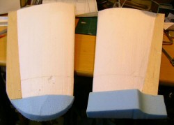
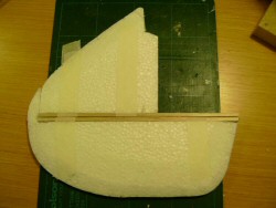
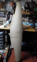
Wing construction.
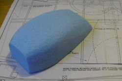
Instead of the built up balsa wing of the Nijhuis plan, I planned to use
a simple hot wire cut foam replacement. This was made in a very similar
way to the Hercules wing, and consists of four separate panels; two centre
sections plus two outer panels.
A balsa trailing edge was added to give stiffness and strength to this rather thin part of the wing. In contrast to the expanded polystyrene used for the wing core, for the wing tips I used an off cut of blue foam. This was a more suitable material than the white foam as it is easier to shape accurately and being denser, it is more resistant to the inevitable scrapes. After shaping, I added a little lightweight filler to cover some of the cutting ripples. The wheel wells were then cut out after which the centre section and outer panels were glued together to from a complete wing.
|
|
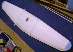
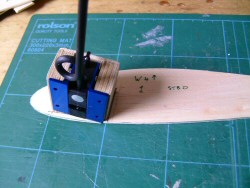
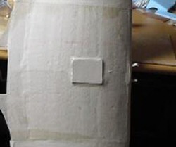
The front wing to fuselage joint is made using two dowels which protrude from the wing's leading edge and locate into holes in a fuselage former in the usual manner. Initially the dowels were simply glued into the white foam of the wing's leading edge. However once the glue had set it was clear that the the white foam was not going to be sufficiently strong to absorb the likely loads of this joint, especially as the wheel well cut outs were close by - any movement of the dowels caused a lot of flexing. To fix this issue, I simply hot wired the leading edge off and glued a piece of hard balsa in its place. I then sanded it to profile and refitted the dowels. This spread the load of the dowels to a much greater area of foam, and the increase in strength was notable and comforting. The last job was cutting and shaping the radiator to fit under the wing.
|
|
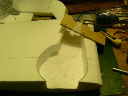
Undercarriage.
I'd not used a retractable undercarriage before, so the wing was going
to be a bit of a learning curve for me. I started the wing by cutting
the wing cores (two inner portions plus two outer portions) and then marked
out the position of the undercarriage wells on the inner cores and cut
them.
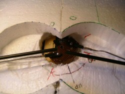
I used the mechanical retracts mentioned in the Nijhuis Hurricane questions thread on the modelflying forum. I cut mounting blocks for them, and also used a balsa rib glued to the blocks to go between the inner and outer cores to spread the stresses across the whole chord of the wing. The block and rib assembly was glued in place on each of the two inner wing panels. Balsa trailing edges were also glued in place, and the two centre wing panels joined. A ply servo mounting panel was glued in place, and the recommended standard 6kg servo was obtained from Robot birds. Making, fitting and adjusting the operating disc from a piece of Veroboard was quite fun, but all got lined up and sorted in the end – the legs went up and down to order!
|
|
Wheels.
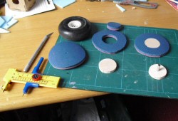
In my 'bits box' I found a pair of wheels the right size - 80mm diameter
and about 30mm thick. However, while playing with the retract system I
found that the retract servo did not cope well with the weight of the
wheels, even though I was using the (recommended) 6kg torque servo. Lighter
wheels were in order, so with an article from an old magazine in mind,
I cut out some 5mm balsa centres and 80mm tyre sections from an old camping
sleeping mat. I used a piece of aerial tube for a axle bush and when assembled
I had a reasonable facsimile of a wheel. The tyres had to be shaped and
painted as blue and pink striped tyres are definitely not scale! The original
wheels weighed 60g while my home made replacements are only 6g! No contest!
|
|
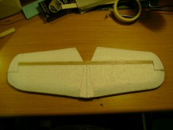
Tail feathers.
I cut a fin and rudder from blue foam, and decided to
weigh it - 11.7g. I cut another from 15mm white polystyrene
foam - 2.6g!!! As the build description in the magazine
suggests that the model tends towards a tail heavy condition,
I went with the white foam components. My experience with
the Hercules suggested that when covered with brown paper,
they would be adequately strong. I then cut and shaped
the tailplane/elevator from 15mm white foam, and fitted
balsa spars to all components for stiffness and hinging.
A bevel was sanded on each of the balsa spars to allow
for hinge movement. Next I dug out some Robart type pin
hinges, two with horns attached, and made fitting holes
in the fin/rudder and tail plane/elevator spars and foam.
|
|
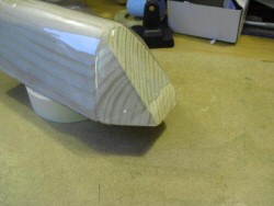
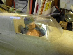
Canopy
I visited Andrew Gibbs to make a wooden mould for the
canopy, as I needed the use of his band saw for this job.
The canopy mould was simply cut from softwood and sanded,
the job taking about half an hour. With two of us, a heat
gun and two pairs of pliers, we then managed to shrink
a lemonade bottle down into a reasonable facsimile of
the Hurricane cockpit. The base of the windscreen ended
up a bit thick and clouded, but the first trim to fit
it to the fuselage got rid of most of that.
|
|
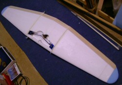
Covering the structure.
I spent the next couple of days applying the brown paper covering to the
airframe. The extra strength and rigidity this provided was quite remarkable,
yet the weight gain seemed minimal. I was interested in quantifying this
observation, so I made a few measurements as I went along. The results
are in the table below:
Comparison of bare and covered weights |
||||
| Item | Weight uncovered |
With paper covering |
Increase in weight | Percentage increase in weight |
| Wings | 365g |
443g |
78g |
21% |
| Fuselage | 352g |
392g |
40g |
11% |
| Tail plane, elevator, fin & rudder | 40g |
67g |
27g |
67% |
As can be seen, the gain in weight for the components was very modest, with the total covering weight amounting to only 145g for the entire airframe. The tail suffered a high percentage increase in weight, but even so this only accounted for a 27g, which was a small fraction of the overall airframe weight.
|
|
Click here for the next part