|
|||
|
|
|
||
| View Shopping Cart |
| Home |
| Guides Available |
| About the Author |
| Reviews |
| Testimonials |
| Free Articles |
| Contact Andrew |
| Terms & Conditions |
| Mailing List |
| Links |
 |
 |
More high quality information absolutely free with every
Gibbs Guides newsletter. Sign up now!
White Diamond
An advanced microlight design concept
Part 1 - The design process
Article by Andrew Gibbs
Introduction
This design study was my final year self-selected project for a degree
in transportation design at Coventry University (then Polytechnic). I'd
always been interested in aircraft design so this project presented an
opportunity to have some fun and indulge that interest in detail.
Although I subsequently became a professional pilot, at the time of the project I'd only been in an aeroplane once, so I had very little real aviation experience to guide me. However, I had already designed a number of successful model aeroplanes, experience which I hoped would help at least to some extent.
The project had to be completed within the available 7 months. I chose to tackle designing a single seat microlight as choosing a 'simple' project seemed a good way of keeping the workload manageable. This was to prove a wise move as the work was to consume almost every waking moment of my life until it was completed.
The design process
Before I could begin work I had a lot to learn about the practicalities
of full size aircraft design, so some detailed research was the necessary
first step. I began by researching some of the available microlight designs
by searching out literature from catalogues, books and so on. This was
before the internet was available, so this research phase took much longer
than it would today. I also consulted two aircraft manufacturers and visited
several airfields to find out what sort of design factors were important
from the pilot's point of view. One thing this revealed that the high
cost of hangarage meant that any design that could be trailed to the airfield
would offer purchasers a considerable saving of money.
|
|
Microlight regulations
For an aircraft to qualify for the microlight category,
it has to satisfy certain regulations. The wing loading
could not exceed 25kg/sq m, and the maximum take-off weight
was 290kg. I decided to design for the maximum allowed
weight, which meant that the wing area had to be at least
11.6sq m (125sq ft).
Design work
I started the design process by making an large number of sketches to
investigate the possible configurations for a new design. One of the things
that quickly became apparent was that the position of the pilot is an
important consideration that can significantly affect the centre of gravity
in very small aircraft since his or her weight is a substantial proportion
of the overall aircraft weight.
One of my objectives was that my design should achieve
a good performance on the limited power available. This meant that efficiency
and drag reduction would be high priority considerations. With these factors
uppermost in mind, I was keen to use a pusher configuration as the conventional
practice (propeller at the front) of throwing accelerated air over the
fuselage wastes energy - a bit like driving a car with the brakes rubbing.
|
|
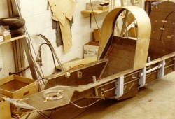
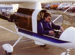
Eventually I hit on the concept from which the final design was derived. Like any design solution, it was a compromise between many factors but it certainly seemed to have potential, as it seemed to satisfy my main criteria of a low drag configuration that offered the promise of good performance, a pusher configuration, excellent pilot visibility, good ergonomics, a low noise footprint and an attractive appearance. I then worked to develop this concept. To help develop the design, I made a full-sized representation of the cockpit, and a radio controlled test model.
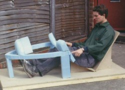
Sitting in a full
sized representation of the cockpit. The idea here was to check
important ergonomic details such as the size, orientation and
location of instrument panels and the pilot's ability to reach
switches and other controls comfortably. |
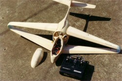
The small radio controlled
test model built during the design phase. Unfortunately, this
was a little too small to learn much of use about the design's
likely flying qualities. |
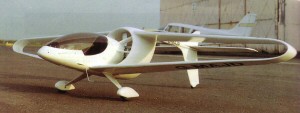
After a lot of work, I was satisfied that I had arrived at a design concept that satisfied my own criteria, and that I also felt would impress the course examiners. It was then time to build a detailed presentation model. The model was to be some 6 feet in wingspan. It didn't have to fly, but it did have to be made to a high standard.
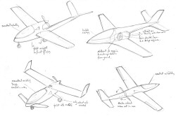
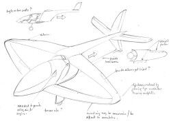
A presentation drawing of
White Diamond, detailing the main points of the proposed design. |
The model was made mainly using wood and vacuum formed plastic. The fuselage sides were made in two halves, each side being vacuum formed over a wooden plug. The canopy was made in a similar way. It took many days to get the mould smooth enough for a high quality canopy to result. The wheel spats were also vacuum formed.
A detailed engine was made, with each cylinder fin made using plastic card. The wings and tail plane were formed from softwood and the control surfaces represented by scribing grooves at the appropriate places.
Once complete, the whole model was primed and prepared for painting. This process alone took over a week. Finally, the model was carefully sprayed using white automotive paint.
|
The presentation model of
White Diamond. This features a detailed interior with the seat,
rudder, pedals, controls and instruments all present. |
This completes this short summary of the design process. Part 2 of this article explains the design concept in some detail:
Click here for the next part