|
|||
|
|
Email
Andrew |
||
| View Shopping Cart |
| Home |
| Guides Available |
| About the Author |
| Reviews |
| Testimonials |
| Free Articles |
| Contact Andrew |
| Terms & Conditions |
| Mailing List |
| Links |
 |
 |
Gibbs Guides.com
More high quality articles and information absolutely
free with every
Gibbs Guides newsletter.
Sign
up now!
Heinkel
He162 Salamander
How a Kyosho T-33 was recycled into a sort-of-Salamander
By Andrew Gibbs
This article was written way back in 2001. It’s still relevant to electric modelling today, so here it is, in a slightly revised format.
This
project eventually
had a successful conclusion,
but it was not without its problems. |
Introduction
I’m one of the many modellers who bought and enjoyed Kyosho’s
T-33. I admire the company for having brought to the market such a bold
and easy introduction to EDF flying. I have been impressed with the model
in many ways – it was quick to build, inexpensive, good looking,
easily hand launched and well mannered in the air. A great combination
of properties and the model was deservedly very successful.
However, the one thing it did not have was a scorching performance. I flew mine about a dozen times and on the recommended 7 nicad cells my example had little more than minimum power to maintain flight. On 8, things improved somewhat but not enough to maintain my interest in continuing to fly the model.
Analysis
of Kyosho’s T-33 design
Examination of the T-33
showed that some elements
of its design were excellent
and others, in contrast,
seemed to be rather poor.
For example, the wing, judging
from the model’s airborne
manners, appeared to be
of excellent aerodynamic
design and was a very light
and beautifully made structure.
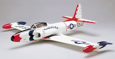 Kyosho’s ground-breaking T33. This all-foam EDF kit made a huge impact when it was released around 2000. |
The fan unit, judging from its appearance and construction, also seemed to be well designed and the motor seemed powerful enough, especially since it was capable of emptying a fully charged pack of 1700SCRs in 3½ minutes.
On the minus side, it appeared that the design of the long ducting was causing a considerable amount of thrust to be lost and that the airframe, while generally clean, had a number of details causing high drag. One example of this was that the wing and tail were both joined at acute angles to the fuselage.
T-33
thrust measurements
I planned to develop the
model in the quest for more
performance. On the T-33’s
box Kyosho claim their fan
unit produces 400g of thrust,
presumably on the recommended
7 cells.
My thrust measuring rig, which I believe to be quite accurate, showed that the installed thrust of my model showed an initial peak of 312g and averaged 277g over the first minute, using a freshly charged 7 cell pack. On 8 cells the initial thrust was 340g and averaged 325g over the first minute. Here are the figures in table form:
T-33 data |
7 cells |
8 cells |
Weight |
1083g/38.2 oz |
1139g/40.2 oz |
Average thrust |
277g/9.17oz |
325g/11.28 oz |
T/W ratio |
25.5% |
28.5% |
Wing area (inc root) |
19.3sq dm / 300sq inches |
|
Wing loading |
56g/dmsq = 18.4 oz/sq ft 59g/dmsq=19.7oz/sq ft |
|
The reason for the model’s lack of performance was now clear– a T/W ratio of 25% is considered the normal bare minimum for flight.
Design
of the new model
I then decided that it would
be more interesting to design
a new model using the best
of the T-33’s components,
i.e. the fan, motor and
beautifully made wing. I
realised that if I could
mate these parts with a
new, lower drag fuselage
and some efficient ducting
then the resulting model
would be significantly livelier
than the T-33.
My design criteria for
the new model were:
1. It should still be able
to be hand launched.
2. It should use at least
some of theT-33’s
components
3. It should be reasonably
simple and easy to modify
if initially unsuccessful
4. If possible, it should
resemble a real aeroplane.
The
full-size He-162
Towards the end of WW2 the
German aircraft industry
produced a number of remarkable
designs. The He-162 was
one of these and was designed
and built in late 1944,
in an incredible time of
a little over 2 months.
This design seemed to have a suitable configuration upon which to base a model – its jet engine was located in a short straight-through duct located on top of a slim fuselage – ideal! It also had extraordinarily small, short wings, but these could be enlarged for the model.
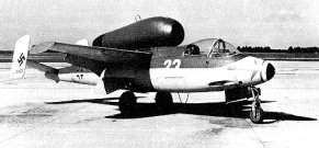 Heinkel’s He163 Salamander. |
It was made largely of wood, a non-strategic material. It weighed up to 5,940 lbs and was powered by a BMW turbojet providing 1,764 lbs static thrust. This gave the machine a T/W ratio of only 30% and consequently it suffered from a relatively poor rate of climb, although it was fast with a top speed of 560 mph at 20,000 feet. Very few of the machines saw active service and of this small number it seems many were lost due to accidents and in-flight break ups. I was hoping for a better record of success, but the project was not to be without a few problems.
I made some sketches and then I drew out a full-sized side view of the new fuselage on an old bit of cardboard box (no expense spared in my workshop). This looked quite attractive (the design, not the box) so I decided to build it there and then from the sketch. This was is in stark contrast to my usual process of drawing up a proper plan and thinking the whole thing through before a knife gets anywhere near balsa.
The wing and tail are both set at +1 degree incidence. I made the tail moment slightly longer than on the donor machine. The thrust line is at +3 degrees to compensate for the high thrust line of the “piggyback” fan position.
I checked that the CG would end up where I wanted it by placing a balsa plank over the side view on the bench. A pencil was located under the plank at the required CG and the plank was balanced with small weights. I then added all the required components and balsa sheets to simulate the weight of the airframe and its contents along the length of the plank. This showed that moving the battery would cater for any likely CG adjustments necessary. No way was this aeroplane going to be carrying any ballast!
Wing
loading
I wanted to reduce the span
of the T-33 wing a little
to get more of the visual
feel of the Heinkel and
also to increase the model’s
roll rate. This decision
would of course reduce the
wing area and consequently
increase the wing loading.
I felt the model would probably
tolerate this provided I
could get the fan to deliver
substantially more thrust,
and if the airframe’s
drag was minimised.
Weight
target
After much weighing of the
components at my disposal,
I set an ambitious target
weight of 1,100g for the
model. Even if the weight
went to 1,200g I felt I
should still have a flyable
model. All wood would be
weighed before use, and
cyano used for much of the
construction.
Construction
- Fuselage
First I set about building
a fuselage from the side
view that I had sketched.
This is a simple balsa box,
using 3/32” (2.5mm)
sides with doublers of the
same thickness. I used a
generous (but light) triangular
section along the corners
so that the shape would
be nicely rounded, for low
drag, when sanded. A fillet
is fitted to the outside
of the wing seat to reduce
the drag of the wing-fuselage
junction.
The canopy is the T-33 item, suitably cut down and stuck to a removable balsa frame so that it becomes the battery hatch. I fitted a sprung locking pin to the rear edge of the frame. Three holes are drilled in the flat front portion of the canopy to admit cooling air.
Motor,
Fan and Pod
The motor pod is made from
the rear of the T-33’s
fuselage. I cut through
the fuselage 15mm aft of
the original motor mounting
slot, and discarded the
last 80mm of this portion.
This gave me a duct about
180mm long, into which I
cut a new motor mounting
slot using a Dremel-type
tool further aft. An additional
30mm of soft balsa was added
to the front of this tube
and shaped to form an elliptical
intake.
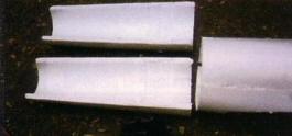 The duct for the Salamander was cut from the rear portion of the T33’s fuselage. |
The overall length of the
completed motor pod is 210mm.
Power was fed to the motor
through a pair of steel
blades that had come from
a windscreen wiper. These
were located one behind
the other and formed a thin
low drag strut. The fan
blades were carefully cleaned
up and the fan checked for
balance. Also the stators
were slightly re-profiled
to try and reduce their
drag.
Tail
plane and Fins
These were simply cut from
5mm thick medium balsa and
shaped to a streamline section.
The tailplane spans 320mm
overall with a root chord
measuring 95mm. Each half
is blocked up 25mm to set
the dihedral. Anti-warp
strips were inserted in
the 125mm high fins.
Wings
Having finished the fuselage,
I still had some doubts
about going for a reduced
wing area. I put these aside
and sawed the wing in to
2 panels, which when placed
together again gave a straight
leading edge, a distinctive
visual characteristic of
the He-162. Each new panel
weighed only 64g, and the
material I had removed weighed
40g including the aileron
torque rods.
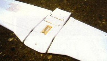 The centre section of the T33 wing was removed to save weight and drag. |
The removed centre section was 105mm wide at the leading edge. I consoled myself that the lost area was less than it appeared since the fuselage was quite narrow in comparison to the T-33 and I had reduced both weight and frontal area. In any case, there was no going back now!!
Each wing was sanded overall and carefully trimmed so that the roots mated accurately with zero dihedral – the top surface of the wings is flat. The panels were then joined with epoxy and joint was reinforced with 1.5mm balsa, also epoxied. A single mini servo and new lightweight linkages were installed to operate the ailerons.
Preparation
for flight
The controls and equipment
were then installed and
the aircraft readied for
its first flight. The speed
controller was located under
the wing, behind the receiver
and in front of the elevator
servo.
I had decided not to paint the machine until I was satisfied it flew well. I range checked it at half power and found that the receiver that I originally planned to use gave a range of only 18 meters with the Tx aerial retracted. However, range improved to 70 meters with a different receiver. I also covered it in cooking foil to give it further protection from its proximity to the speed controller. I used the rest of the foil in the preparation of a tasty roast dinner that I put it in to the oven for my supper! In my excitement to fly the model, I forgot to photograph it or put it on my TMR. The ready to fly weight had come out at 1,100g approx with an 8-cell pack.
First
flight – April 1st
2001
I range checked the machine
again at the field at half
power: 70 meters again with
aerial down. The equipment
inside the machine was the
same as I had used in the
T-33 and I felt confident
that all would be well.
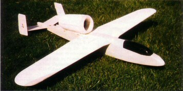
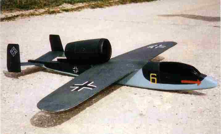
 Confident the model would fly well, it was nevertheless tested without paint, just in case. A wise precaution as it turned out |
The model was hand launched into a light southeasterly wind. It was slightly sluggish for a second or two and then climbed away strongly. A little trimming of the controls saw it flying smoothly around, and I felt confident to try loops and rolls. All who saw it were very impressed with its performance. It was easily able to maintain height on half power and loop from level flight. A couple of times the motor slowed momentarily before regaining full power, but other than that, no problems were evident.
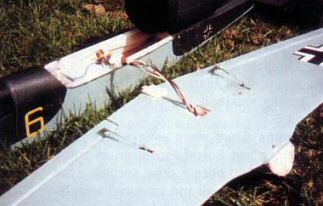
I continued to enjoy myself but then suddenly, at a distance of only about 50 meters away with down elevator selected, the Salamander stopped responding to the controls. I attempted to pull up and shut the motor off but without success. I could only watch as my beautiful aeroplane developed an almost vertical dive in to the concrete runway from some considerable height. The entire airframe was wrecked – wings broken in two, fuselage all broken up, tail snapped in three places, flight battery and aileron servo both totally smashed up. Strangely, the nylon M4 wing bolt was undamaged. I felt thoroughly dejected. My dejection was all the worse because I had not photographed the finished model or measured its thrust on my thrust rig.
 Ouch! After the first flight. |
Back home things went from bad to worse – my roast dinner had burnt! However, all was not lost. In some ways the day had been a great success – the aircraft had flown very well and appeared aerodynamically sound. And I had not invested any time in painting it!
After consuming the edible
portions of my dinner, I
went to my workshop to survey
the wreckage in search of
clues. I could not definitely
ascertain the cause of the
crash, but, being brutally
honest with myself, the
cause was probably something
for which I was somehow
responsible. After much
thought and discussion,
the following theories were
formed as reasons for the
disaster:
1. The speed controller
BEC function had failed.
2. Loss of signal due to
the transmitter aerial pointing
directly at the model (this
would give a very weak signal
in the direction of the
model)
3. The elevator linkage
had become disconnected
in flight.
4. The battery pack had
moved during the negative
g manoeuvre
5. Radio interference
6. Poor equipment installation,
particularly the speed controller’s
position, sited as it was,
amongst the rest of the
gear.
I also discovered that the balsa in the vicinity of the blade supplying motor power had become burnt, which I could not account for.
Rebuilding
In spite of the extensive
damage, I decided to rebuild
the model. Amazingly, this
proved to be a much quicker
affair than its initial
construction. The wing was
epoxied back together and
a spar inserted locally
across the break to help
carry flight loads. I also
applied 2 thicknesses of
tissue with dilute PVA across
the centre third of the
wing to help reinforce the
joint.
At this point I decided to replace the single aileron servo with a pair installed one in each wing. This would give the ailerons the ability to act as flaps - this might be useful since the model’s wing loading was climbing still further with the weight of all the repairs!
The wrecked fuselage was rebuilt, this time with a better battery retention system (Velcro and small polystyrene locating blocks) and an all-new elevator linkage. I installed a dual conversion receiver with a new crystal, again wrapped in foil. A new elevator servo was fitted, relocated to just behind the receiver. The speed controller was relocated well to the rear and away from any other radio equipment, to a position directly under the motor. The motor was fitted with additional suppression, now comprising 3 capacitors, and a diode across the motor terminals. The BEC function of my speed controller was disabled and an 110mAh NiMh receiver battery installed behind the cockpit canopy.
The receiver aerial had originally been routed through the fuselage. It was now re-routed out through the wing to keep it away from the motor and speed controller – and its weight also helped balance the weight of the epoxy repairs in the other wing! I wired both wing servos and the aerial through a de-shelled 9-way computer D plug so that the wing could be conveniently removed, taking great care to ensure that the effective aerial length was not altered.
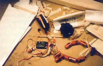
 The rebuild took a long time. Here's the repaired airframe, before painting. |
I felt that I had now done everything I could to minimise the chance of a repeat of the disaster. Since the model had flown well (apart from the landing!), it was now time to paint it.
Finishing
I applied a dope and lightweight tissue covering to the fuselage. This
added only 12g. The foam motor pod also had tissue applied, but with dilute
PVA to avoid melting the foam. Once dried
 The servos and receiver aerial are routed through the wing. For convenience, a single 9-way computer 'D' connector was used to connect the fuselage-to-wing wiring. |
out, this was lightly sanded and a covering of dope applied. Several coats of dope were also applied to the tissued area of the wing. The whole model was then painted with Tamiya acrylic colour, which added about 10g.
Markings were also painted on, using enamel. Lastly, I added panel lines using the method described by Chris Golds in his excellent April EFI article. I was very pleased with the model’s finished appearance. It certainly looked a lot better than at the conclusion of its first flight!
 Finally, the model was fully repaired and painted. Painting really brought it to life. |
Testing!
I was very disappointed to discover that the weight of the model had crept
up to 1,204g - and elated to find that the TMR revealed that the initial
static thrust was 480g, and averaged 445g over the first minute. This
gave an average T/W ratio of 37%.
Also the mystery of the hot blade had been solved: the steel was getting very hot due to the current flowing. Realising that the steel blade was a material with an electrical high resistance, I replaced the it with thick copper wire and re-tested it – no more heat and even more thrust – over 500g initially!!! This result showed that Kyosho’s claim of 400g thrust for their fan unit was justified, if it was efficiently installed.
I then checked every possible detail of the whole model and completed all necessary measurements and photographs. I also decided that on all subsequent flights, the transmitter aerial will never be pointed at the model and that any sign of a malfunction, however slight, will be designated reason enough for an immediate landing.
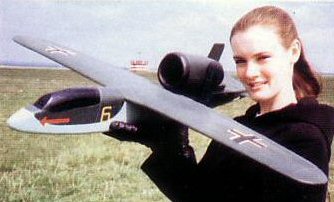
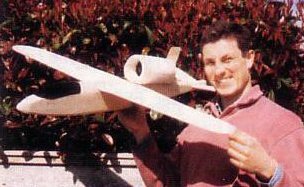
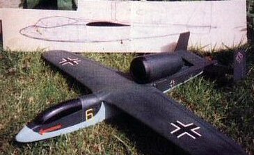 The sort-of-Salamander, and the sketch from which it was built. Very few people recognise the model’s origins. |
More
flying
The model was tested again
on a windy 22 April. Prior
to flying, I decided that
I would not point the transmitter
aerial at the model, even
if it was close by, and
that I would immediately
land at any sign of a malfunction,
however slight.
In spite of the weight increase, the performance was at least as good as before. The model seemed relatively unaffected by the wind, probably due to its relatively high wing loading. Climb rate and level flight speed were good. It was able to loop from level flight and it had a good rate of roll. However, the flaps, although they gave no trim change when deployed did not seem very effective. By comparison with the T-33, I estimate top speed in level flight is about 50% greater, speed in a dive about double. The flight time was 6 1/2 minutes, about half of which was ambling around at low power for photos.
Conclusion
This was an enjoyable and satisfying project and my aim of producing a
capable model using the parts from the T-33 was satisfied. I am looking
forward to flying the model a lot more. The project taught me a lot about
EDF and probably even more about persistence! Grateful thanks are due
to Chris Golds for sharing his knowledge both through his writings and
via his telephone.
Comparison of the Salamander and the T33: |
||
Salamander (rebuilt) |
T-33 |
|
Length |
940mm/37" |
|
Wing span |
1055mm/41.5" |
45.5" |
Root chord |
210mm/8.25" |
greater |
Tip chord |
118mm/4.6" |
118mm/4.6" |
Wing area |
17.3 dm sq/266 sq inches = 1.847 sq ft |
300 sq in |
Weight |
1,204g /43oz |
1,139g/41oz |
Wing loading |
70g/sq dm/23.28 oz/sq ft |
19.7oz/sq ft |
Thrust |
480g |
320g |
T/W ratio |
39.8% |
28% |
Tail span |
320mm/12.6" |
|
Average tail chord |
95mm/3.75" |
|
Tail area |
3.04dm sq/47sq inches = 17% wing area |
|