|
|||
|
|
|
||
| View Shopping Cart |
| Home |
| Guides Available |
| About the Author |
| FAQs |
| Testimonials |
| Articles |
| Contact Andrew |
| Terms & Conditions |
| Mailing List |
| Links |
 |
 |
More high quality information absolutely free with every
Gibbs Guides newsletter. Sign up now!
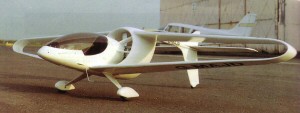
White Diamond
An advanced microlight design concept
Part 2 - The design described in detail
Article by Andrew Gibbs
The design solution
Like any design, the final solution arrived at was a compromise between
many factors. The whole airframe is designed so that when disassembled
it can be carried on a trailer of road-legal width to save on hangarage
costs.
White Diamond general arrangement
(GA) drawing. This scale drawing gives dimensions and shows the
location of all the main parts of the design. |
Wings
The diamond wing arrangement was chosen to combine structural advantages
of the biplane, namely a high strength/weight ratio, without the disadvantages
of high drag and poor visibility inherent in conventional biplane designs.
I was delighted when a detailed research paper came to my attention
that supported this theory.
The tapered, swept and staggered (upper and lower wings spaced longitudinally) surfaces of the diamond wing, while structurally superior even to a biplane are effectively monoplane surfaces aerodynamically: each wing should operate almost free of interference from the other, except for the small wing tip region, so one of the chief problems inherent in biplane design of wing interference is largely avoided. The position of the wings one in front of the other imparts a measure of longitudinal stability, which means the tailplane area can be reduced a little. This arrangement is also tolerant of a wider range of CG positions than a conventional layout. At 11.6sqm, the wing area is the minimum to maintain the maximum allowed wing loading of 25kg/sqm at the maximum design weight of 290kg.
The diamond
wing arrangement was chosen to try and combine structural advantages
of the biplane without the usual aerodynamic disadvantages of biplane
designs. A high aspect ratio should mean low induced drag. |
By joining the wing
tips together, induced drag may be lower than for either a conventional
monoplane or for a biplane. White Diamond does not use any bracing
struts or wires. |
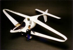
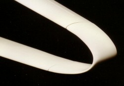
Low induced drag (the drag created by generating lift) is achieved by using a high aspect ratio wing combined with taper, giving a favourable span-wise lift distribution. The joined wing tips are designed to further reduce induced drag by eliminating tip vortices as far as practically possible, the theory being: no wing tips - no wing tip vortices. Safe stall characteristics should be achieved by using a slightly thicker section in percentage terms towards the wing tip, combined with washout.
The wings are of composite sandwich construction, where a strong, thin skin of fibreglass is combined with a very light foam or honeycomb core, whose main function is to stiffen and space the load bearing skins apart. The wing tips are similarly constructed, with the addition of anti-shear ribs. Incidentally, the principle of sandwich construction is nicely illustrated by a well-refrigerated Crunchie bar - the structure is light, stiff and strong!
The wings are split into 4 light and easily manageable panels for easy assembly and disassembly. The upper and lower panels are nearly identical which helps lower production costs.
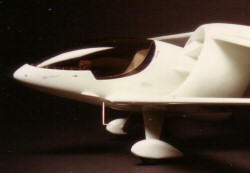
Fuselage
The fuselage is also of composite construction and would be moulded
Airfix style in 2 vertically split halves. Each half has the
lower wing root integrally moulded and is stiffened by the addition
of a box section made from honeycomb sheet and an internal spar to which
the lower wings and undercarriage are later fitted. A glass/foam firewall
is located towards the rear of the fuselage pod to which the engine
is fitted using a steel tube mount. The firewall is locally reinforced
at the mounting points to prevent crushing. The canopy is front-hinged
and so is naturally held shut in flight. It incorporates an internal
frame housing instruments and de-mist air ducts. The fuel tank and luggage
compartment are located behind the pilot's seat.
The fuselage
is of composite construction and would be moulded 'Airfix'
style in 2 vertically split halves. |
The canopy
is front-hinged. The fuel tank and luggage area are located
at the CG just behind the pilot's seat, making it almost impossible
to load the aircraft to an out of balance condition. |
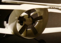
The fan duct is also of composite construction, being formed from inner and outer shells. The outer shell incorporates integrally moulded upper wing roots. The duct is first fitted to the fuselage using steel tubes which serve both to align the whole assembly accurately and later help maintain its shape in use. Load bearing glass fibre vanes are bonded in place afterwards, completing the assembly. The boom is a hollow filament wound composite structure of comparatively thick wall to carry flight loads and the forces transmitted by the fin during taxiing.
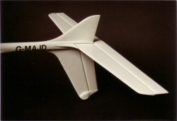
Tailplane and boom
The fin and rudder are deliberately the only parts of the airframe to
project into the accelerated airstream from the fan. This was desirable
to help provide directional control while taxiing and taking off in crosswind
conditions. The horizontal tailplane is detachable and is of entirely
conventional steel tube construction. The non-detachable fin projects
mainly downwards and houses the tailwheel. The lower fin is of sturdy
composite construction since it must take taxiing and landing loads.
White Diamond tailplane.
The tailwheel is located in the base of the fin. |
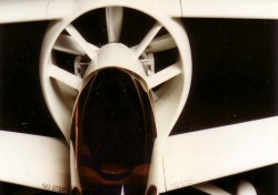
White Diamond's ducted
fan unit. The engine exhausts may be see underneath the spinner. |
Choice of a ducted fan system
Research revealed that microlights were often operated from private airstrips.
These present a significantly different operating environment than licensed
airfiields. From a safety perspective, I had two main concerns; firstly,
loose surface debris is commonplace, and represented a danger to conventional
propellers. Secondly, I discovered that since private airfields were unregulated,
they permitted anyone to be present near aircraft and consequently were
associated with a much greater risk of a member of the public walking
into a rotating propeller.
A ducted fan propulsion system offered a solution to these problems, especially as it could be located behind the lower wing. Other good reasons for choosing a fan system are that it is quiet in terms of noise footprint and efficient at the speeds expected - according to the highly regarded reference work 'The Design of the Aeroplane' a fan is quieter and more efficient than a propeller up to about 110kt, after which the drag of the duct itself becomes limiting. Although the calculated maximum speed of White Diamond on 60hp would be around 130kt, its cruise speed would be about 100kt, which would use a fan to best advantage.
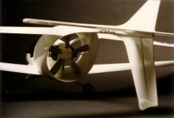
The lower wing
is located forward of the ducted fan; this helps to prevent the
fan from ingesting ground-borne debris and ejecting it at high speed.
This arrangement also helps to prevent any bystanders from accidentally
walking into the fan. |
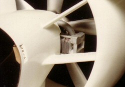
Emdair
CF077A 60hp four stroke engine. The induction manifold can be seen
above the cylinder head. Research
indicated that a fan would be more efficient than a prop, though
I have come to doubt this claim. The duct and vanes would inevitably
be a significant source of drag. |
Engine selection
I wanted to avoid the use of the then common Rotax 2-stroke engine, both
because my research indicated that pilots seemed to experience a lot of
engine failures using these, and because of it's environmentally poor
total-loss lubrication system. Instead, I chose the twin cylinder 60hp
4-stroke Emdair CF077A. This offered better fuel economy than a 2-stroke,
meaning increased range and savings in oil costs, although these advantages
were partly offset by the 4-stroke's inherent weight penalty. Alternatively,
almost any engine of 45-80hp could be substituted, particularly as the
engine is located very close to the CG.
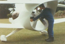
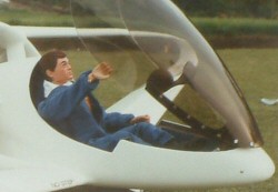
White
Diamond's Action Man pilot is seen here performing a thorough
pre-flight inspection. The engine is equipped with an electric
starter. It would probably be difficult and dangerous
to hand swing a ducted fan engine into life. |
Fans
are inherently quieter than conventional propellers. This is partly
because the engine sound is partially contained is within the
duct, and because the fan blades are effectively tipless due to
the close proximity of the duct wall. |
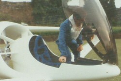
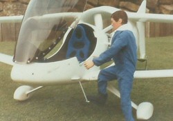
Entry and egress
Getting in and out is easily achieved through the combination of well
positioned steps, a convenient grab handle and the large fully-opening
canopy, which raises the instruments with it, further easing access.
The seat slides to accommodate differing pilot sizes. Each seat position is marked with its corresponding minimum and maximum pilot weights. Smaller, lighter pilots naturally sit further forward helping to keep the CG within safe limits. The baggage area is located at the CG so it would be very difficult to load the aircraft in an out of balance condition. Similarly, the fuel tank is located at the CG so the trim of the machine will not alter significantly as fuel is burnt off.
The
conveniently positioned steps make for easy access to White Diamond's
cockpit. |
The
instrument binnacles are attached to the opening canopy, so they
are well out of the way when the pilot is getting in or out of
the cockpit. |
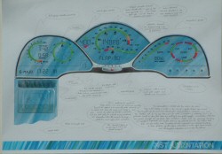
Cockpit and instrumentation
Once seated and with the canopy closed, the pilot is presented with
three instrument binnacles; a large central one, located in the nose
of the aircraft and two smaller less distant ones. The main flight instruments
are displayed on the central binnacle at increased size to compensate
for their distant position. The remaining instruments of less critical
importance (e.g. engine instruments) are on the two nearer displays.
The large main instrument display is located at a significantly greater distance than is usual from the pilot's eyes. This means that re-focussing from infinity (outside) to instruments is a much less 'stressful' task for the eyes since far less visual accommodation is necessary, greatly alleviating the eyesight problem that so many older people have to contend with and whom may well comprise a significant proportion of White Diamond pilots. An additional feature of the main instrument display is that the lower range of airspeeds, which is of particular importance during landing, is displayed on a seperate expanded scale.
The overall effect of this instrumentation concept is to enable a close watch of both airspeed and outside matters to be kept virtually simultaneously, bringing a particular advantage at critical stages of flight such as during approach. In effect it could be said to be a sort of head up display.
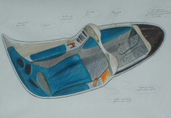
Drawing
showing the cockpit layout of White Diamond. The controls all fall
neatly to hand, while the instrumentation concept incorporates some
new ideas. |
Drawing showing a view
the of instrumentation as seen by a seated pilot. The primary instruments
are located on the central binnacle, requiring less visual accommodation. |
Central to the instrumentation concept is an on-board computer. Inputs to the computer would include the fuel level, flap setting, angle of bank and manually entered inputs such as pilot and baggage weights. These inputs allow the computer to accurately estimate the 1G stall speed, which varies with weight. This value would be displayed as a floating point indicator on the expanded airspeed scale. The computer would also display the flight time elapsed and flight time remaining based on current fuel consumption. Additionally, engine and carburettor temperatures would be displayed, and a warning given if carburettor icing became likely or if engine overheating was imminent. Even today carburettor icing is a significant problem for general aviation aircraft and it seemed to me then that a simple temperature gauge would offer a worthwhile safety benefit.
Controls
A side stick situated on the right hand side of the cockpit operates conventional
elevator and aileron controls via cables which run through the duct vanes.
The vanes are very strong and are reinforced to maintain structural integrity
of the airframe and protect the control runs in the very unlikely event
of the fan bursting. The throttle and flap controls are located on the
left side of the cockpit. The cockpit is comfortable, being roomy, quiet,
fully enclosed and fitted with a padded seat. For summer use an alternative
half-length canopy could be fitted for the pleasures of open-cockpit flying.
Visibility is excellent during taxi, level flight and turns due to the
large canopy and the virtual absence of any airframe forward of the pilot.
Since all of the heavy masses (pilot, fuel and engine) are located around the CG, the machine should be reasonably manoeuvrable in all three axes. The maximum take-off weight is 290kg with an 85kg pilot, 10kg of baggage and a very generous 50 litres of fuel aboard, enough for 5 hours to dry tanks.
A white paint finish was chosen, as the reflective properties of white are necessary to prevent the composite structure from overheating in strong sunlight. Looking at the finished design, the choice of name became very easy!
| White Diamond technical data | ||
| Span | 8.53 m | 24 ft 4 in |
| Length | TBA | TBA |
| Maximum flying weight |
290 kg | 639 lbs |
| Wing Area | 11.6 sq m | 125 sq ft |
| Wing Loading | 25 kg/sq m | 15 lbs/sq ft |
| Fuel capacity | 50 litres / 11 UK gallons | |
| Endurance (est) | 4hr 30min plus 30min reserve | |
| Engine | Emdair CF077A 1,261cc 4-stroke | |
| Fan | 115 cm diameter, 5 blades | |
| Max Power | 65hp (48.5kW) | |
| Estimated max level speed | 240 km/h | 130 kt (149mph) |
| Estimated cruise speed | 185 km/h | 100 kt (115mph) |
| Power Loading | 167W/kg | 76W/lb |